From Mexie ... to MXSE ...
Moderators: timk, Stu, -alex, miata, StanTheMan, greenMachine, ManiacLachy, Daffy, zombie, Andrew, The American, Lokiel
-
Okibi

- Speed Racer
- Posts: 10910
- Joined: Thu Aug 21, 2003 11:00 am
- Vehicle: NB SE
- Location: Perth, Western Australia
- Contact:
Re: From Mexie ... to MXSE ...
I see an intercooler upgrade in your near future 

If you had access to a car like this, would you take it back right away? Neither would I.
-
KevGoat

- Speed Racer
- Posts: 3968
- Joined: Sun Jun 17, 2012 8:48 pm
- Vehicle: NB SE
- Location: Down South, Adelaide, SA
Re: From Mexie ... to MXSE ...
Okibi wrote:I see an intercooler upgrade in your near future
Been in my eBay watch list for a while, but I keep buying other stuff
-
KevGoat
- Speed Racer
- Posts: 3968
- Joined: Sun Jun 17, 2012 8:48 pm
- Vehicle: NB SE
- Location: Down South, Adelaide, SA
Re: From Mexie ... to MXSE ...
Simple mod, big improvement ...
All credit ... How-To: 3rd Gen Mitsubishi Eclipse Dash Vents in an NB
I picked up some Mitsi Eclipse vents from eBay USA. Not only are these more functional, they look better as well.

They need to be cut down to similar length of the stock vents

The position of these two clips is important.

They coincide with the first indent on the Mitsi vents. But I found that, once I had clipped mine into the dash, if I rotated them, they'd just pop out. Very annoying. So I went back to Google and found one post that mentioned filing a groove that will not only hold them in better, but also allow easier rotation.
This groove is filed in just above the indent like this ...

Now when fitted, the vent rotates easily and stays fitted in place!
So, better airflow, better direction, better looks and most importantly my wife can close off her vents and stop nagging me when I want that cold air on me ...


-
fastfreddygassit

- Waitin' for a mate
- Posts: 1773
- Joined: Sat Jun 25, 2005 8:00 pm
- Vehicle: NB SE
- Location: Waitin' for a mate in Melbourne somewhere
- Contact:
Re: From Mexie ... to MXSE ...
Great job! 
If you don't mind me asking, what was the cost including shipping?
If you don't mind me asking, what was the cost including shipping?
-
KevGoat
- Speed Racer
- Posts: 3968
- Joined: Sun Jun 17, 2012 8:48 pm
- Vehicle: NB SE
- Location: Down South, Adelaide, SA
Re: From Mexie ... to MXSE ...
Hi there Mike! ... I got them for AU$60 shipped. The seller said they had some marks on them, but the photos didn't show anything that I could see, so I took the chance against the others that were about $20 dearer. When they arrived they were virtually perfect, just dusty!
I almost mucked the first one up by cutting too much off!! What's that measure twice cut once thingy?!! For anyone doing this, cut just above the holes for the internal flap that gets removed (or just read the "how to" better than I did )
)
I almost mucked the first one up by cutting too much off!! What's that measure twice cut once thingy?!! For anyone doing this, cut just above the holes for the internal flap that gets removed (or just read the "how to" better than I did
-
fastfreddygassit
- Waitin' for a mate
- Posts: 1773
- Joined: Sat Jun 25, 2005 8:00 pm
- Vehicle: NB SE
- Location: Waitin' for a mate in Melbourne somewhere
- Contact:
Re: From Mexie ... to MXSE ...
*starts searching eBay.....*
-
KevGoat
- Speed Racer
- Posts: 3968
- Joined: Sun Jun 17, 2012 8:48 pm
- Vehicle: NB SE
- Location: Down South, Adelaide, SA
Re: From Mexie ... to MXSE ...
It would appear my SE has gained a name ... since fitting the BEGi CAI, I've been referring to it as Muttley ...
-
KevGoat
- Speed Racer
- Posts: 3968
- Joined: Sun Jun 17, 2012 8:48 pm
- Vehicle: NB SE
- Location: Down South, Adelaide, SA
Re: From Mexie ... to MXSE ...
Fitted the Tribute spray nozzles obtained through the group buy organised by guss_bruss. No photos ... they, ummmm, look like spray nozzles ... but, yeah, the spray pattern is much better than the standard jet sprays.
Then decided I'd check the working of the turbo wastegate. Since fitting the CAI, I've been a bit concerned at some high boost figures on the gauge. Lokiel had mentioned to me during some past communications that it would be worth checking the wastegate as they are known to have issues. Connected up a small air compressor and at first there didn't seem to be any movement. Then after trying again, it moved, and from then on it continued to moved freely. I'm wondering if, due to lack of use by the two previous female owners - the last owner of 5 years being 75 years old when she traded it in! - the wastegate had very little, if any, use! Haven't dríven it yet, so we'll see if it makes any difference ....
Lastly ... Muttley's BOV/CAI snickering has a downside ... my wife is not so keen on the car's sense of humor. I decided I'd try to insulate the inside of the CAI cover and see if that reduced some of the sound. Nup ... virtually no difference So I got hold of a short strip of door rubber and fitted that. Combined, it has made some difference. Haven't dríven it with the wife installed, so we'll see if has made enough difference

Then decided I'd check the working of the turbo wastegate. Since fitting the CAI, I've been a bit concerned at some high boost figures on the gauge. Lokiel had mentioned to me during some past communications that it would be worth checking the wastegate as they are known to have issues. Connected up a small air compressor and at first there didn't seem to be any movement. Then after trying again, it moved, and from then on it continued to moved freely. I'm wondering if, due to lack of use by the two previous female owners - the last owner of 5 years being 75 years old when she traded it in! - the wastegate had very little, if any, use! Haven't dríven it yet, so we'll see if it makes any difference ....
Lastly ... Muttley's BOV/CAI snickering has a downside ... my wife is not so keen on the car's sense of humor. I decided I'd try to insulate the inside of the CAI cover and see if that reduced some of the sound. Nup ... virtually no difference

-
Lokiel

- Forum legend
- Posts: 4126
- Joined: Thu May 28, 2009 2:39 pm
- Vehicle: NB SE
- Location: Brisbania
Re: From Mexie ... to MXSE ...
Surely the wife make more noise than the CAI 
You could try some sound deadening insulation inside the airbox too - FM sells this and I'm sure you could find something locally for a DIY solution. I planned to do this initially but the noise never bothered me so I never did it. Bonus points if you find something to line the box that deadens sound AND provides heat shielding.
Regarding the wastegate: The MSM/SE's wastegate isn't known to have issues but KevGoat's symptoms made me wonder if his was actually seized shut. In an earlier life I had a Mitsubishi JA Starion that had a LOT of punch; when I got the turbo serviced they explained that it was due to the seized wastegate valve, probably because the PO hadn't used the car in a while - I was quite disappointed when I got my car back Testing this is simple enough, just attach a pump/compressor to the wastegate actuator's barb and pressurize it to verify that the shaft moves sufficiently.
You could try some sound deadening insulation inside the airbox too - FM sells this and I'm sure you could find something locally for a DIY solution. I planned to do this initially but the noise never bothered me so I never did it. Bonus points if you find something to line the box that deadens sound AND provides heat shielding.
Regarding the wastegate: The MSM/SE's wastegate isn't known to have issues but KevGoat's symptoms made me wonder if his was actually seized shut. In an earlier life I had a Mitsubishi JA Starion that had a LOT of punch; when I got the turbo serviced they explained that it was due to the seized wastegate valve, probably because the PO hadn't used the car in a while - I was quite disappointed when I got my car back
Don't worry about dying, worry about not living!
Garage Thread: http://www.mx5cartalk.com/forum/viewtopic.php?f=57&t=76716
Garage Thread: http://www.mx5cartalk.com/forum/viewtopic.php?f=57&t=76716
-
KevGoat
- Speed Racer
- Posts: 3968
- Joined: Sun Jun 17, 2012 8:48 pm
- Vehicle: NB SE
- Location: Down South, Adelaide, SA
Re: From Mexie ... to MXSE ...
Yeah I did fit sound insulation inside the airbox. That worked a little, but a lot less than I expected (cheap crappy ebay stuff), though it did improve the type of sound - similar to insulating a speaker box, which I suppose it is in this sense. Now has a deeper growl sound than a tinny echoey sound 
Your idea of using the air pump worked great! I don't know what's inside a wastegate, but I'm hoping that having now got it moving smoothly, it will keep moving
Your idea of using the air pump worked great! I don't know what's inside a wastegate, but I'm hoping that having now got it moving smoothly, it will keep moving
-
Lokiel
- Forum legend
- Posts: 4126
- Joined: Thu May 28, 2009 2:39 pm
- Vehicle: NB SE
- Location: Brisbania
Re: From Mexie ... to MXSE ...
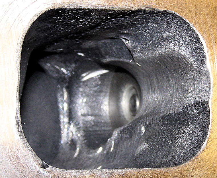
Here's a great photo for illustrating how an internal wastegate works since all the components are shown clearly:

Exhaust gas enters the compressor chamber via the flange shown on the bottom left.
The "flapper valve" on its right is the wastegate valve. On the bottom right you can see the rod that pivots it open and closed, as well as where the wastegate actuator's shaft attaches to it so that the shaft can be rotated (opening and closing the valve).
Normally the wastegate valve is shut so ALL exhaust gas flows into the turbo's exhaust chamber which spools the compressor wheel; the air then exits the compressor chamber into the dump pipe which attaches to the flange facing you in the picture above.
When the wastegate valve opens, some of that incoming exhaust gas can exit directly into the dump pipe so the turbo will not continue to spool up as fast and will slow down if the wastegate opens enough.
Mild boost creep issues on low-boost turbos can be solved by porting the exhaust housing's channel to the wastegate valve:
In the middle you can sort-of see the face of the wastegate valve. Here the DIYer has used a grinder to create a smoother airflow to the wastegate outlet. Air tends to flow along walls so will mostly rush over the 90* wastegate outlet without this at no-to-low boost levels (at high boost levels this is less of an issue since the added pressure means it's easier for the air to flow out the wastegate outlet than into the highly pressurised compression chamber - this is why the advice "To avoid boost creep, increase your boost level!" exists; unfortunately if you only want low boost levels, this does not apply).
If your wastegate valve is seized shut, the turbo will continue spooling as the exhaust gas pressure increases - there will be a ceiling but it will be MUCH higher than the 12-14psi celing typically used with MSM/SE IHI turbos.
Another nice picture, courtesy of mazda-speed.com's mr_hyde:
Don't worry about dying, worry about not living!
Garage Thread: http://www.mx5cartalk.com/forum/viewtopic.php?f=57&t=76716
Garage Thread: http://www.mx5cartalk.com/forum/viewtopic.php?f=57&t=76716
-
KevGoat
- Speed Racer
- Posts: 3968
- Joined: Sun Jun 17, 2012 8:48 pm
- Vehicle: NB SE
- Location: Down South, Adelaide, SA
Re: From Mexie ... to MXSE ...
Appreciate the images and explanation. Simpler internal workings than I'd imagined.
Looking back, the stuck wastegate must have been why it hit boost cut a couple of times back when the car was still stock. No idea what the boost was actually rising to back then though. The fact that it only happened a couple of times is just a sad testament to my 'ol fart driving ...
Looking back, the stuck wastegate must have been why it hit boost cut a couple of times back when the car was still stock. No idea what the boost was actually rising to back then though. The fact that it only happened a couple of times is just a sad testament to my 'ol fart driving ...
-
KevGoat
- Speed Racer
- Posts: 3968
- Joined: Sun Jun 17, 2012 8:48 pm
- Vehicle: NB SE
- Location: Down South, Adelaide, SA
Re: From Mexie ... to MXSE ...
Some birthday goodies arrived ...
Since one of my wheels is slightly buckled and requires re-rolling, and all of my tires need replacing soon, I'd been trying to decide what direction to go. So far, I hadn't seen much that I liked enough to replace the stockies, then last week I saw davekmoore had a set of SE RH's with near new tyres available for not much more than the cost to replace my tyres, so decided that was a handy answer for me for now ... thanks Dave
With the two near perfect wheels from my set and two similar ones from this set, I have one perfect set plus one set with a few marks. So, as I really like the design of these wheels and still think they "make" the car, I might consider having the marked set fixed up and re-sprayed in a darker colour, just to "toughen" the car's overall look a little.

Yup! ... these arrived today as well ...

Since one of my wheels is slightly buckled and requires re-rolling, and all of my tires need replacing soon, I'd been trying to decide what direction to go. So far, I hadn't seen much that I liked enough to replace the stockies, then last week I saw davekmoore had a set of SE RH's with near new tyres available for not much more than the cost to replace my tyres, so decided that was a handy answer for me for now ... thanks Dave
With the two near perfect wheels from my set and two similar ones from this set, I have one perfect set plus one set with a few marks. So, as I really like the design of these wheels and still think they "make" the car, I might consider having the marked set fixed up and re-sprayed in a darker colour, just to "toughen" the car's overall look a little.

Okibi wrote:I see an intercooler upgrade in your near future
Yup! ... these arrived today as well ...

-
luzinit
- Fast Driver
- Posts: 287
- Joined: Sat Oct 12, 2013 8:27 am
- Vehicle: NB8A
Re: From Mexie ... to MXSE ...
Are the two sets different colours or are they a perfect match?
Sent from my SM-G920I using Tapatalk
Sent from my SM-G920I using Tapatalk
-
KevGoat
- Speed Racer
- Posts: 3968
- Joined: Sun Jun 17, 2012 8:48 pm
- Vehicle: NB SE
- Location: Down South, Adelaide, SA
Re: From Mexie ... to MXSE ...
Actually, good question! Hadn't looked that closely yet. Have read that there are some variations. I'll check that.
Sent from my GT-I9100T using Tapatalk
Sent from my GT-I9100T using Tapatalk
Who is online
Users browsing this forum: No registered users and 29 guests


