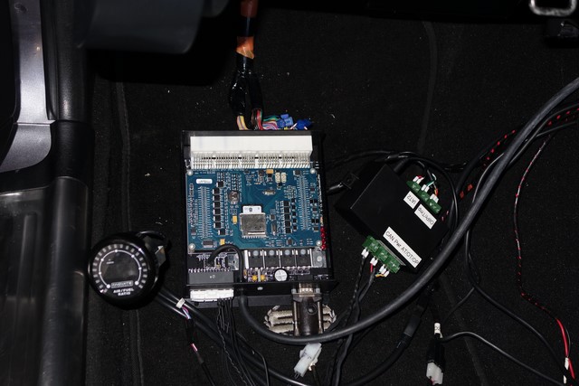
Originally posted by Lokiel, Sun Sep 24, 2017 5:36 pmOriginally posted by Lokiel, Tue Jan 10, 2017 11:18 pm[Over the Xmas break I mounted my MS3-Pro properly in the passenger's footwell under the kickplate using a DIY bracket made from galvanised iron.
It went so smoothly and quickly I didn't even take the time to take photos (I usually do this between breaks).
I don't use my Pioneer Double-DIN head unit much in my MX5 and mostly used it on long drives to listen to podcasts or music.
After installing an Eonon Android head unit in my SP23 and really liking its versatility, I decided to install an Android head unit in Gina.
My only issue with the SP23's Android unit is its screen resolution, 800x480(WVGA), which isn't enough when you have Apps with buttons on them or clutter the screen with icons.
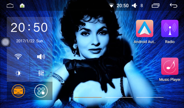
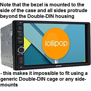
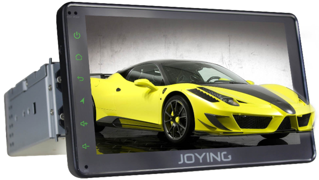
You can get 1024x600 units now so I ordered a Pumpkin Double-DIN unit, similar to this one from Joying:
I got it prior to Xmas and spent 3 days trying to install the bastard in Gina and here are the problems with it:
1. The unit comes with NO mounting hardware - so I bought a generic Double-DIN cage.
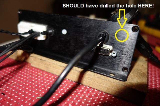
2. Double-DIN units are heavy and name-brand manufacturers include a rubberised mounting pin on the back that slides into a slot in the cavity's rear vertical brace to help support the unit.
This wasn't included but there was a threaded hole in the rear at approximately the right spot so I made a mounting pin from a 5mm Allen bolt, several nuts and multiple layers of heatshrink "heatshrunk".
3. The plastic fascia that comes with the unit looks cheap and looks like it's been sitting in the sun for years - it's NOT black.
The fascia is far too wide and a little tall too so you need to trim it a lot, way too much on the sides though because it becomes too thin. I have several fascias from other units but none fit over the unit due to the next problem:
4. The front plastic bezel attaches to the outside of the metal housing so protrudes on all sides.
This means that the unit CANNOT be mounted in the generic cage because the plastic bezel stops it sliding far enough forward, meaning that the unit sticks out way too far. Good luck with trying to make your own custom solution too because the plastic bezel is so wide that there's no room on the sides so you can't get any extracting tools in to get it out again if you have snap-lock tabs. There is quite a bit of vertical space though.
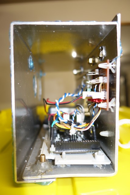
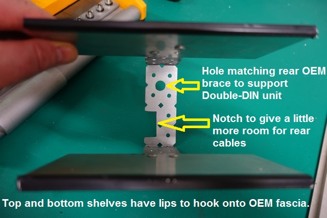
Since there is no room on the sides, I made a top and bottom shelf out of 2mm aluminium with small lips on the front to hook onto the fascia and joined them with a square-angled u-brace that was mounted to the cavity's rear brace and included a hole for the mounting pin to pass through, The unit slid in and sat well but protruded a little too far for my liking but that was going to be as good as it gets. I still had NO idea how I was going to secure it in place, custom locking tabs onto the top and bottom shelf were going to be my only option.
Some of the rear cables plug in close to that rear vertical cavity brace so I connected them and slid the unit in for a test fit - unfortunately they prevented the unit from going all the way. Most of the offending wiring was audio and since I only have from speakers and an amp in my car, I cut off all the unwanted wires from the plug and STILL had the same problem - the socket is hitting the rear brace so can't go in fully.
I'd spent a few days on this trying to figure out how to make it work but at this point I realised it was impossible and put the Pioneer unit back in.
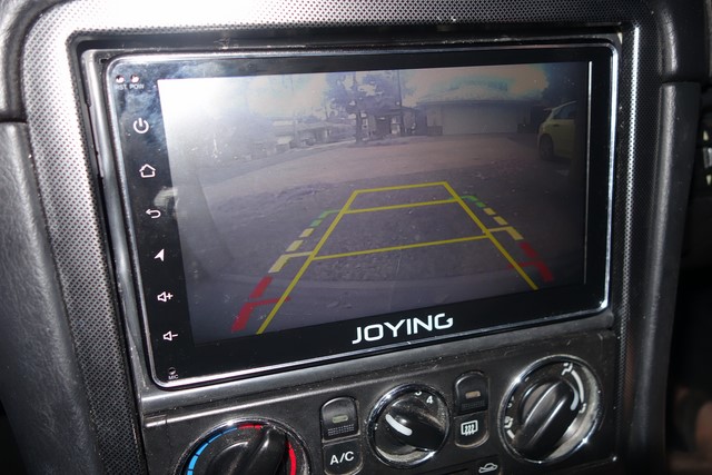
Originally posted by Lokiel, Wed Jan 11, 2017 12:16 am[After a few days, I'd cooled down over the Double-DIN Android fiasco and got on eBay to see what else was available and found this 1024x600 Joying Single-DIN unit:
The screen is detachable, has multiple vertical mounting points and is shallower than most Double-DIN units so I figured I should be able to fit it - somehow.
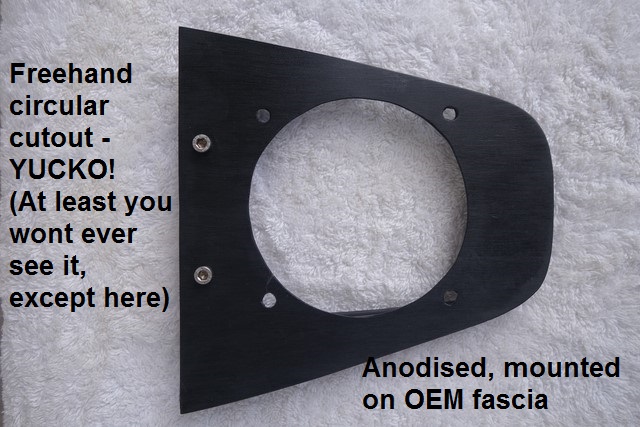
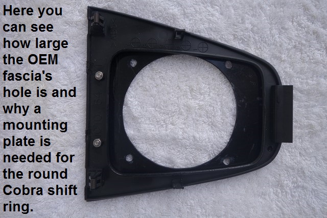
The unit has a single-DIN mounting cage which latches onto the OEM fascia.
Unfortunately because of this, the detachable screen sticks out too far, I wanted it flush with the fascia.
Luckily the screen fits inside the NB's Double-DIN cavity so I figured I should be able to come up with something:
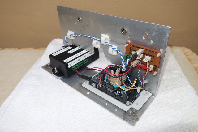
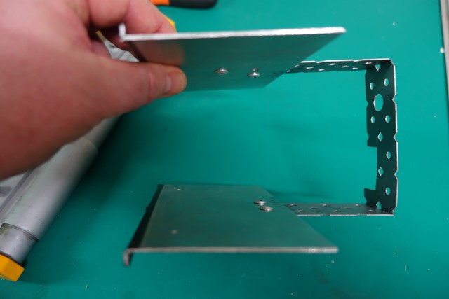
DIY mounting braces:
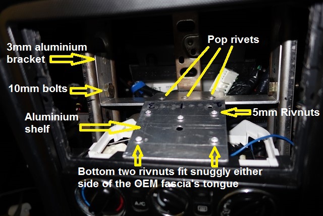
- that rear 3mm aluminium bracket is an absolute bitch to get in since those OEM side vertical braces have rolled edges and the brace fits flush against the recessed flat centre section.
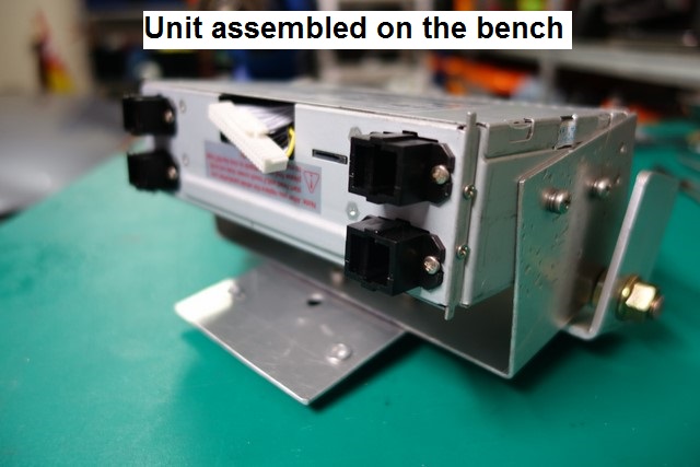
Head Unit bracket:
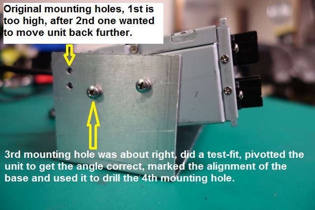
- getting the angle correct was time-consuming, the unit needs to be solidly mounted to get it right
- the unit must be inserted sideways into the cavity, then rotated into place
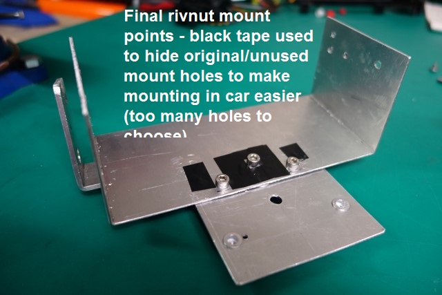
Here's how the brackets connect:
- getting the depth correct was time-consuming, once again, the unit needs to be solidly mounted to get it right
- I used Allen bolts since they were the only 5mm bolts I had on hand
To tighten those three Allen bolts when the single-DIN unit was in place, I needed to mod a spare Allen key to shorten it:
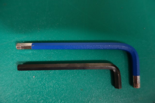
- I've got heaps of these from various kits in the past, glad I didn't just throw them out.
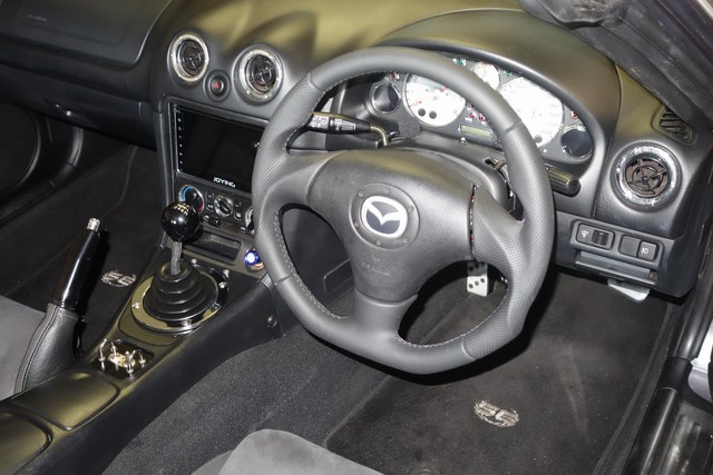
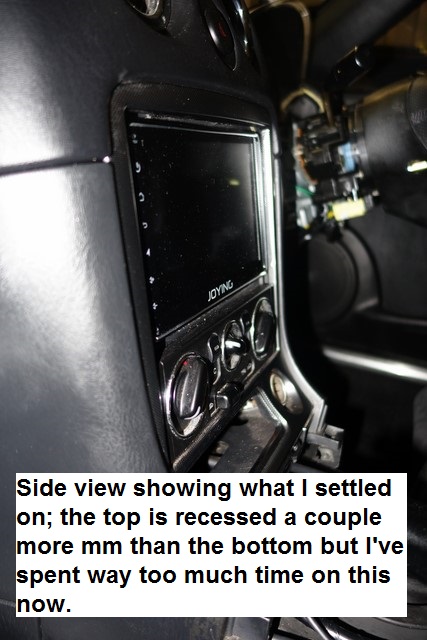
Side view with the screen attached:
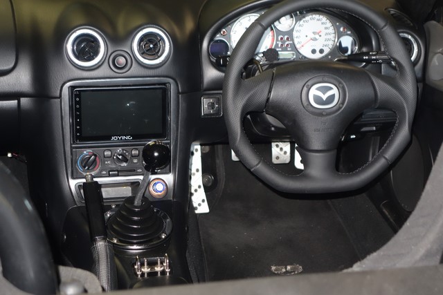
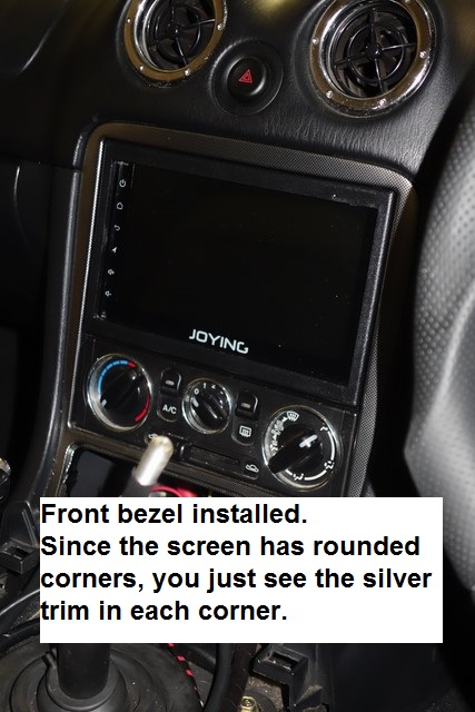
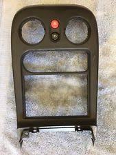
Front view, no bezel:
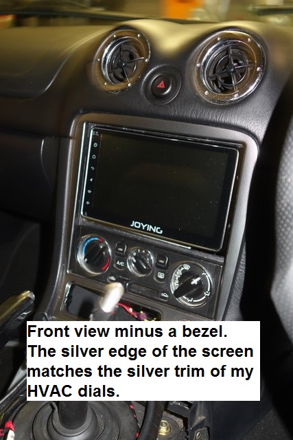
- I really like this look so might just mask the unsightly gaps behind the screen (ie. a DIY bezel behind the screen)
Front view with bezel:
I spent a lot of time figuring out where to mount the GPS unit.
On my SP23 there's a hidden flat shelf above the centre console, underneath the dashboard that seems just made to place a GPS unit.
There's nothing like this in an NB so I toyed with the idea of placing it on the rear parcel shelf or mounted on the dashboard as far forward as possible, near the driver's A-pillar.
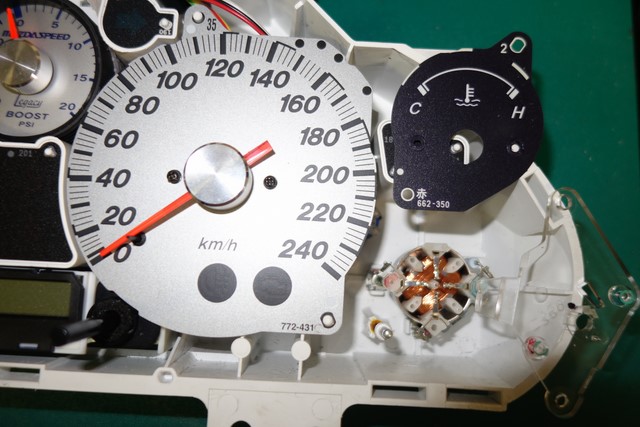
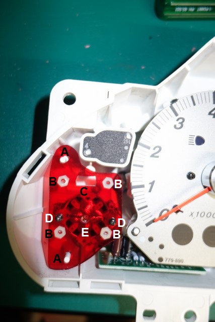
Didn't like any of these options so pulled apart the instrument cluster to feel if there was any space under the dashboard (there's none on the passenger side with the airbag in the way).
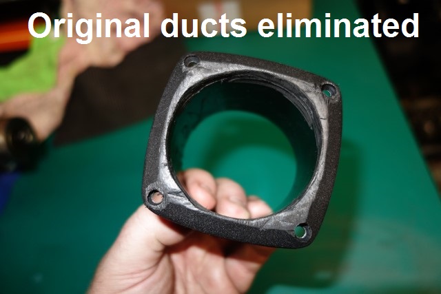
The best place I could actually access was on top of the right centre air vent tunnel - picture the rounded instrument cluster hood, it's forward of the hood at about the 10 o'clock position.
I used velcro to mount the GPS on top of the air vent tunnel - if you don't think that's strong enough I say BOLLOCKS! Trying to get the GPS unit positioned correctly was a pain in the arse in that cramped space, every time the velcro surfaces touched they'd lock tight and I'd have to get them apart again.
I found using an old credit card between the velcro surfaces worked well, once the GPS was in about the right spot, I slid the credit card out.
That GPS unit isn't going anywhere.
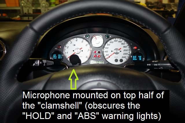
Still not sure about where to put the microphone - very useful for Andoid voice commands.
The A-Pillar seems to be the most common place but that would look odd since it looks like a small round foam ball - like a "booger".
Originally posted by Roadrunner, Wed Jan 11, 2017 8:28 am[For the microphone, I routed mine up and over the steering column and poked it out in the cluster surround near the Odo reset button. Used a bit of black double sided tape to hold in place.
Seems to be ok there but there people I speak to do complain there is a bit of wind noise. Where ever the ND has its mic is the spot to put it. I've spoken to the wife when she's been at 110kph on the freeway roof down and its like she's in a quiet room. Maybe also the ND mic is a far better quality unit than my Pioneer one.
How does the screen go for glare with the roof down? Looks great btw!
Originally posted by ManiacLachy, Wed Jan 11, 2017 8:33 am[Your ingenuity know no bounds! However, you've convinced me to give up on the idea of an Android unit for the time being. Far too hard and fiddly for me.
Originally posted by Snowmotion, Wed Jan 11, 2017 9:14 am[I mounted my remote mic for hands free on top of the steering column cover towards the edge closest to the instrument cluster. people can hear me perfectly with the top down so seems pretty good.
Originally posted by Lokiel, Wed Jan 11, 2017 9:42 am[Snowmotion wrote:I mounted my remote mic for hands free on top of the steering column cover towards the edge closest to the instrument cluster. people can hear me perfectly with the top down so seems pretty good.
Thanks for that verification - I was concerned about wind noise on the A-pillar which was another concern.
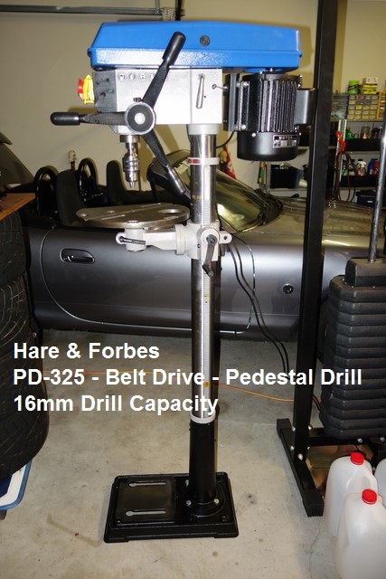
Originally posted by Magpie, Wed Jan 11, 2017 9:58 am[Nice fabrication skills, I seem to recall that you purchased a bench bender. Will the car be exposed to any UV rays in 2017
 Originally posted by Lokiel, Wed Jan 11, 2017 10:00 am[
Roadrunner wrote:For the microphone, I routed mine up and over the steering column and poked it out in the cluster surround near the Odo reset button. Used a bit of black double sided tape to hold in place.
Seems to be ok there but there people I speak to do complain there is a bit of wind noise. Where ever the ND has its mic is the spot to put it. I've spoken to the wife when she's been at 110kph on the freeway roof down and its like she's in a quiet room. Maybe also the ND mic is a far better quality unit than my Pioneer one.
How does the screen go for glare with the roof down? Looks great btw!
Thanks for the info.
Believe it or not, I haven't even fired the unit up yet!
After my previous failed attempt at fitting the Double-DIN Android unit, I didn't want to waste any time "dicking around" with the new unit if I couldn't even fit it (rage level was at EXTREME when I gave up on the Double-DIN unit after spending so much time trying to fit it - was close to smashing it to pieces with a hammer).
I do expect glare to be an issue though, even the best Android phones can be hard to read in the sun - this is a Chinese screen so it can't compare to them.
I may try making a hood if the glare is too bad - will need to be acrylic though and NOT aluminium for safety reasons.
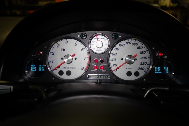
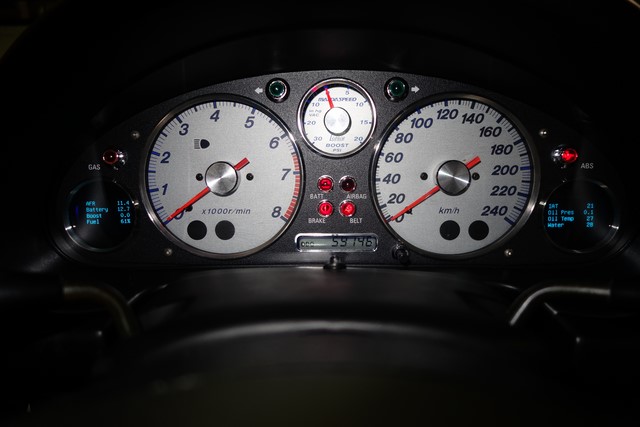
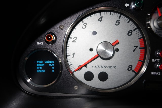
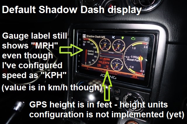
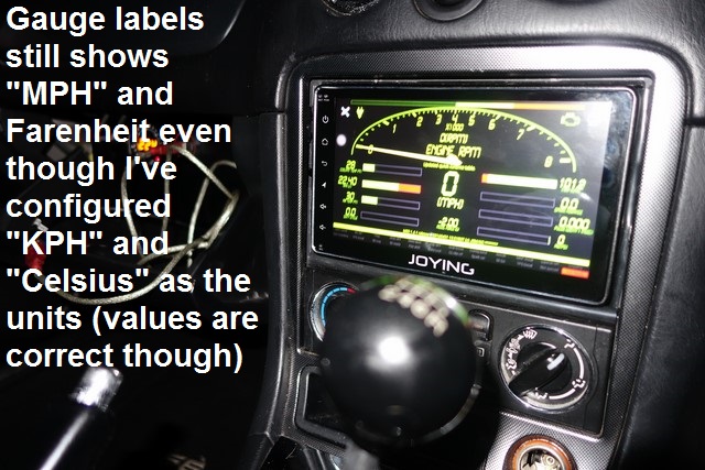
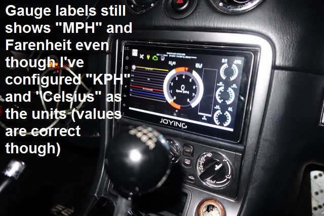
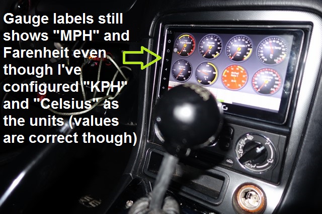
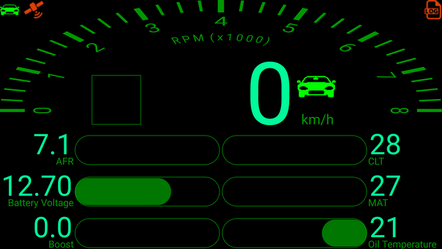
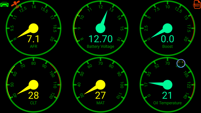
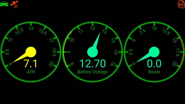
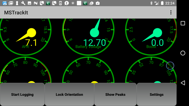
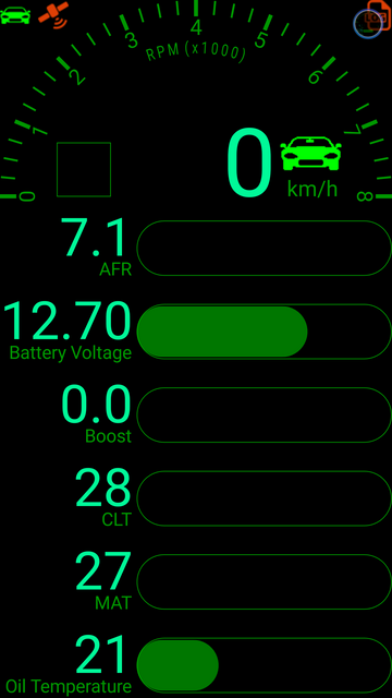
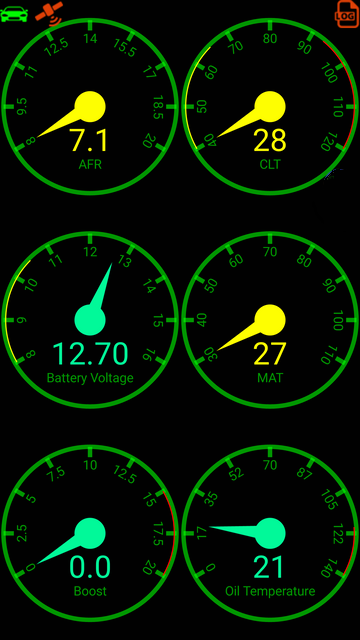
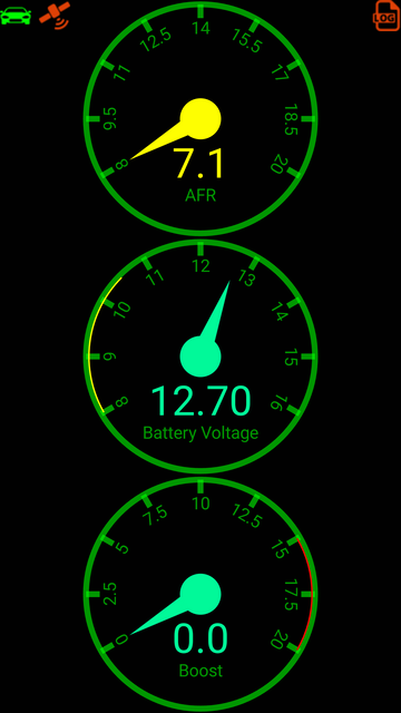
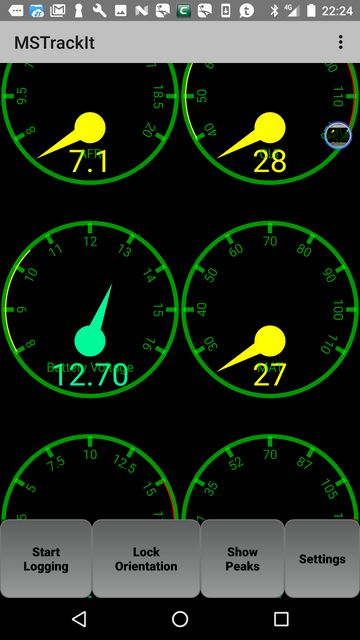
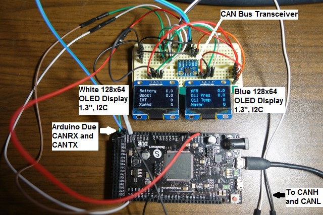
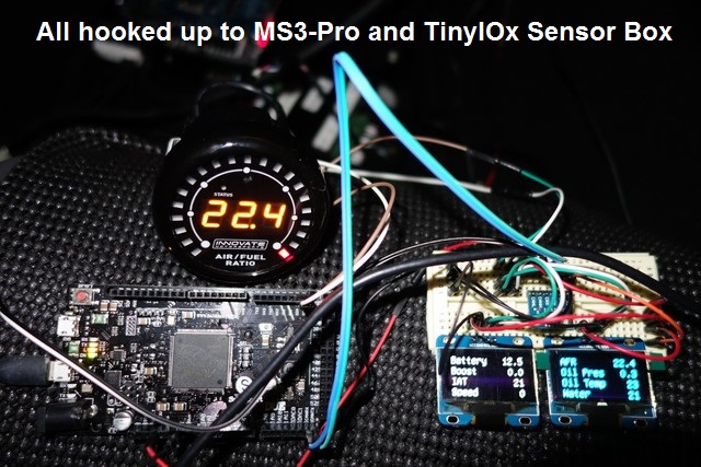
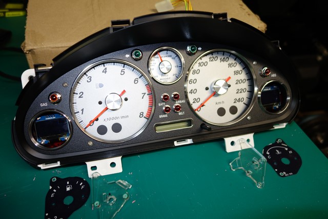
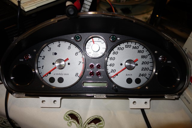
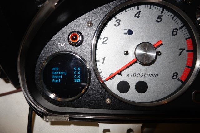
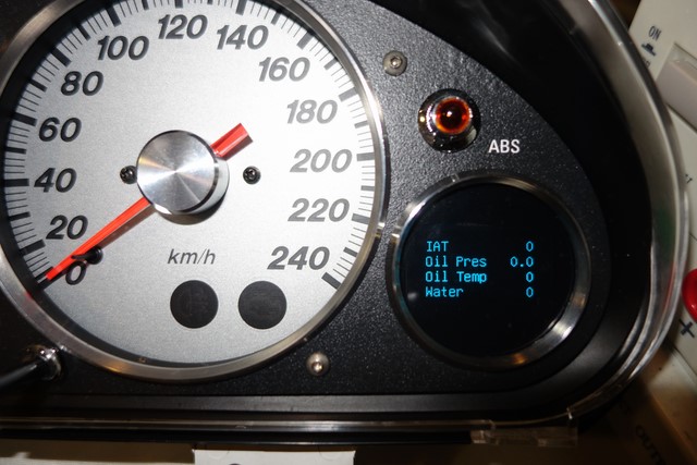
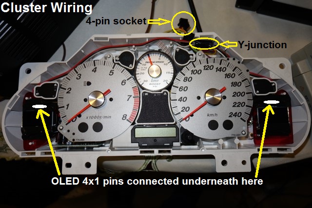
I have my blue OLED instrument cluster gauges now so the important stuff can be read there - the Android unit will be used mostly for its GPS and to control MS3-Pro logging (I wont be trying to read the MS3-Pro data from it, that's on the OLED gauges).
Originally posted by Lokiel, Wed Jan 11, 2017 10:10 am[Magpie wrote:Nice fabrication skills, I seem to recall that you purchased a bench bender. Will the car be exposed to any UV rays in 2017
That's the plan.
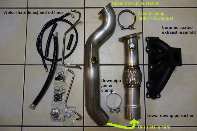
I've got all the TSE turbo+manifold+downpipe bits now. I was waiting on a shim for the TSE downpipe since they found that the initial downpipes leaked and needed it - this arrived in November.
I have one of the original EFR6258 turbos which was sand-cast.
Unfortunately this means it was very rough and that the recommended manifold->turbo Stage 8 fasteners couldn't be used on it.
MX5 Plus used Nissan locking tabs on it but I'd prefer the Stage 8 fasteners since they've been track-proven and I should never need to worry about them.
The newer turbos are no longer sand-cast so are finished better and will accomodate the Stage 8 fasteners so I've ordered the exhaust housing which will arrive in 3-4 weeks (I hope - damn the Xmas shutdown period!)
I also had to look at the newly occurring airbag flashing light and the ABS flashing light (which used to occur once in a while but occurs all the time now).
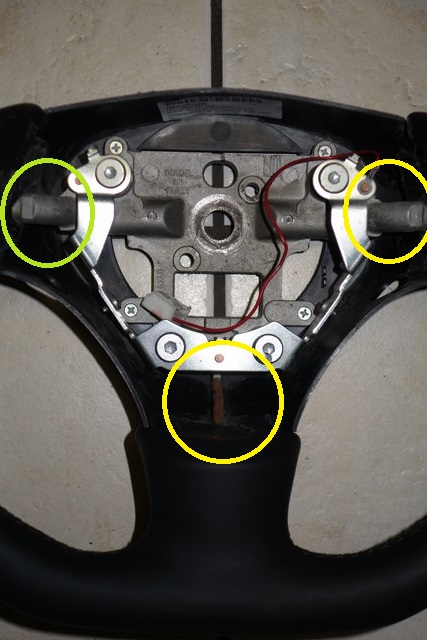
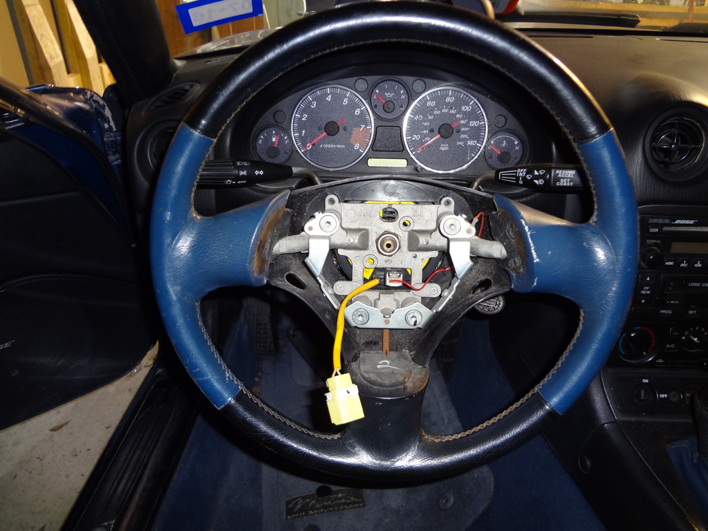
The airbag flash code was for the steering wheel's airbag and I diagnosed it down to the clockspring thanks to the workshop reference manual.
I bought a 2nd hand one on eBay but while waiting for it I pulled out my original clockspring and did all the connectivity tests which were fine.
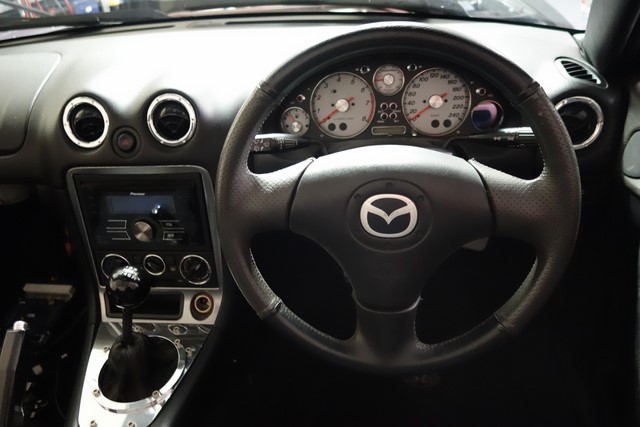
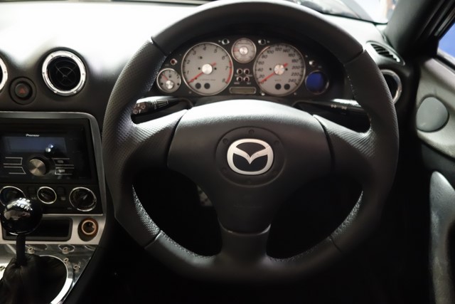
I re-installed it, aligned it correctly, torqued the steering wheel up to spec and the fault disappeared.
I guess when I installed the new steering wheel that I paid no attention to aligning the clockspring correctly or over-torqued the steering wheel.
The ABS flash code is for the front left sensor so I ordered a new one which I'm still waiting for.
Originally posted by Lokiel, Wed Jan 11, 2017 10:44 am[ManiacLachy wrote::
However, you've convinced me to give up on the idea of an Android unit for the time being. Far too hard and fiddly for me.
This took way too long and I would recommend finding a wrecked NB's front dash and removing the side panels so that you can get at the rear and sides when working out the positioning and angles required for the brackets. I spent a lot of time on my knees, holding my body in un-natural positions while working in the cramped cavity.
I think there's a market for this bracket, it could just be made in 2 pieces of laser-cut aluminium, one for the brace and another for the Single-DIN unit.
Originally posted by Lokiel, Wed Jan 11, 2017 1:00 pm[Roadrunner wrote:"
Where ever the ND has its mic is the spot to put it. I've spoken to the wife when she's been at 110kph on the freeway roof down and its like she's in a quiet room. Maybe also the ND mic is a far better quality unit than my Pioneer one.
:
This thread shows the ND solution; unfortunately it's not simply a microphone positioning issue:
https://forum.miata.net/vb/showthread.php?p=7613910&highlight=microphone#post7613910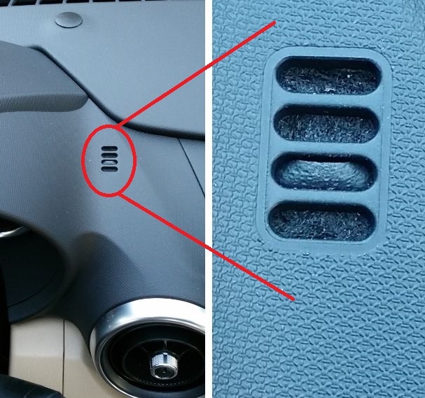 Originally posted by bruce, Wed Jan 11, 2017 9:46 pm[
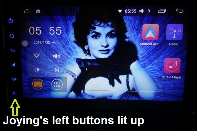
You've gotta cover/mask that JOYING badge.
Originally posted by Lokiel, Wed Jan 11, 2017 11:37 pm[bruce wrote:You've gotta cover/mask that JOYING badge.
LOL = it's under the glass so not easy to do.
On the other hand, it works as a built-in theft-deterrent system - who'd try and steal a Chinese head unit made by some company called Joying?
It's definitely not name-brand so any re-sale value is minimal.
Originally posted by Magpie, Thu Jan 12, 2017 7:14 am[They would have to steal it from your garage as its not as if it is left alone (or even allowed) outside
Originally posted by ManiacLachy, Thu Jan 12, 2017 7:48 am[Magpie wrote:They would have to steal it from your garage as its not as if it is left alone (or even allowed) outside
It's low hanging fruit, but I laugh everytime!

I thought the same thing about the massive "JOYING", when the first product shots were posted, but once it was installed it didn't look quite so in your face. Keen to see it running MSDroid or ShadowDash.
Originally posted by Magpie, Thu Jan 12, 2017 8:07 am[I cannot resist it
However, in all seriousness Lokiel's build, like Pham's the attention to detail is amazing. Plus Lokiel is prepared to share what worked and more importantly what did not.


 )
)